

Make sure you have all parts pictured here. Listed from top to bottom, left to right, in the picture shown :
A   1 5" length of 22 gauge wire
B   2 RGB LEDs
D   2 68Ω resistors ( blue grey black gold brown )
C   1 10KΩ or 100KΩ resistor ( brown black black orange brown )
E   1 2xAAA battery pack
F   1 pre-programmed AtTiny24 microcontroller
G   1 14 pin DIP chip socket
H   1 8-pin right angle male header
I   1 Visor controller printed circuit board
J   1 Blue LED
K   1 Ultraviolet LED
L   1 toggle power switch
M   4 tactile switches
N   2 4-pin female jumper cables

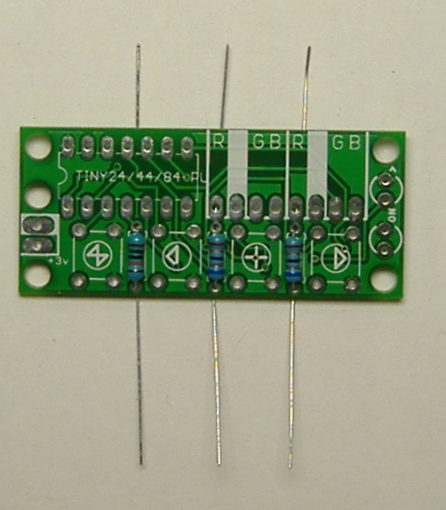
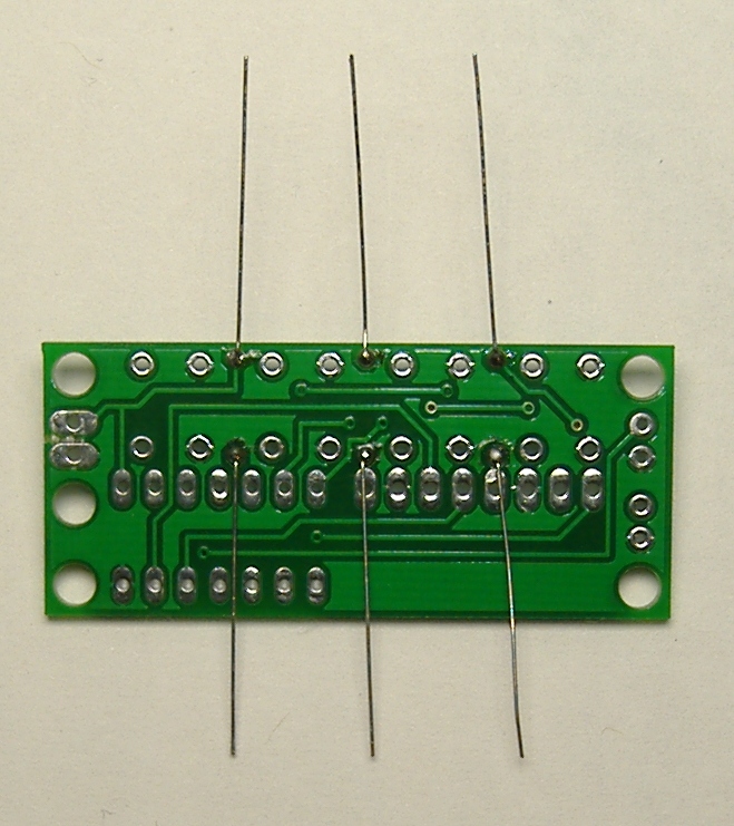
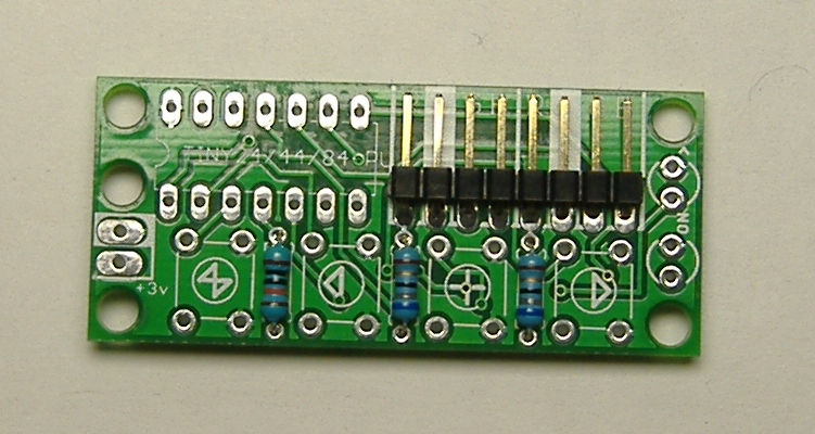
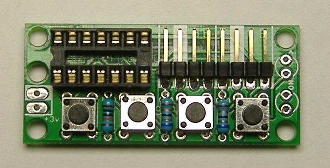
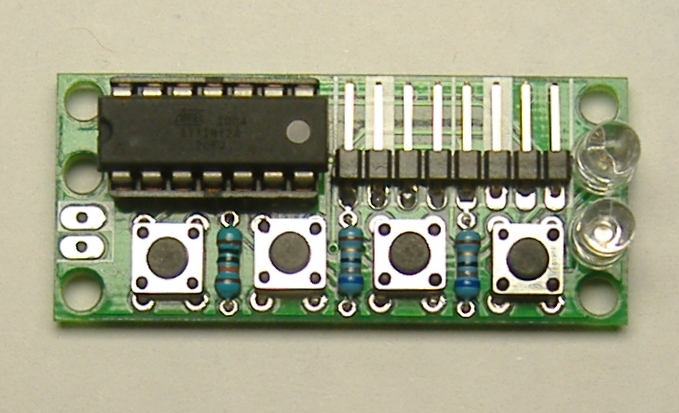
Locate the three resistors and bend the leads at a right angle close to the body, as shown. The LED resistors are 68Ω ( blue grey black gold brown ). The reset pull-up resistor is 100KΩ ( brown black black orange brown ). Insert the resistors into the board. The two 68 ohm resistors go on the right, at shown, in the slots marked "LED". The reset pull-up resistor goes in the slot on the left marked "10k". Optionally bend the leads outward to hold the resistors in place while you solder them. Solder the resistors, and trim the excess leads with a wire cutter.

Place the 8-pin right-angle connector for the RGB LED cables as shown. Note that the plastic part of the header should surround the part of the header that is parallel to the board. Turn the board over and solder the 8-pin right angle connector. A common trick to get the connector flush against the board is to solder one pin. Then, melt that solder joint while pressing the connector flush against the board, and let it cool again. Solder the remaining pins.


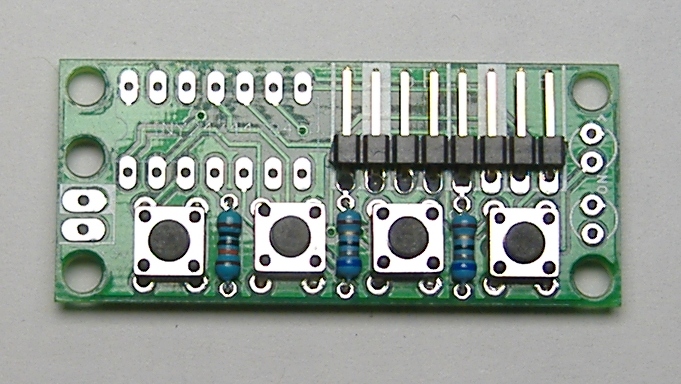
Place the tactile switches on the board as shown. Note that, if the tactile switches are places sideways, the board will not function. Turn the board over and solder the tactile switches in place.


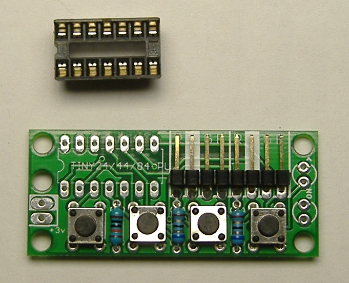
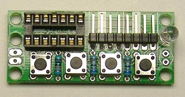
Solder the chip socket. Note that there is a U shaped notch in one side of the socket. This indicates the orientation of the socket. Place the socket so that this notch is on the left as shown. One trick to get the socket flush against the board is to solder one corner pin, then melt that solder joint, position the socket so that it is flush, and let the joint cool. Then, do the same thing on the opposite corner. The socket is now held in place, leaving you free to solder the remaining pins.
Solder the indicator LEDs. It is important to insert these LEDs in the correct direction, otherwise they will not light. The LED has two leads. One leads is the "ground" LED. This lead will be shorter. IF you look closely at the plastic part of the LED, the base on one side will be flat. This also indicates the side of the LED with ground lead. In our case, thr ground lead should be at the top, as pictured here. Solder both indicator LEDs. One will be purple and one will be blue, but it does not matter which one goes where.


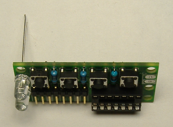
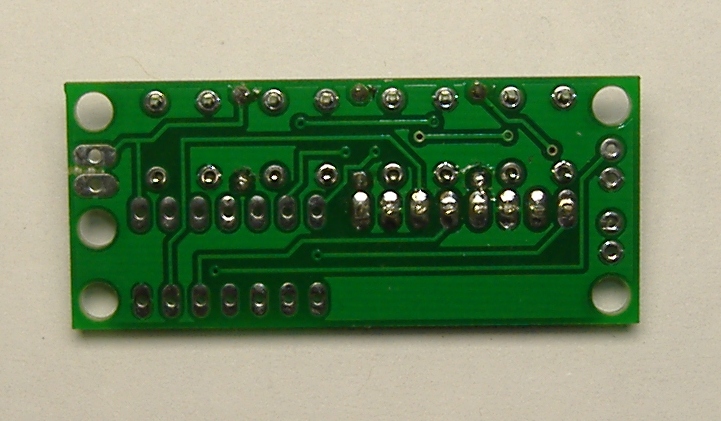
Trim any extra leads sticking out of the bottom of the board with wire snips.

Locate the AtTiny24 microcontroller chip. Note that one end of the chip has a U shaped notch, just like the socket. This indicates the orientation of the chip, and it is important to insert the chip in the correct orientation, otherwise the board will not work. The notch should be on the left as pictured. Carefully insert the microcontroller into its socket.

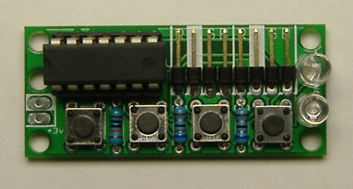
This completes the board assembly phase of the project.
Project Stages:
- The Visor
- Phase I : The Board
- Phase II : The Optics
- Phase III : Holes
- Phase IV : Power
- Phase V : Light
- Phase VI : Finish and Play
- Usage Notes