

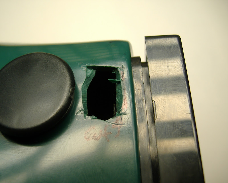
Observe the markings in this picture. You can attach the electronics in many creative ways, but this is the way I assembled it. Wherever you decide to place the board, cut a small slit for the power wires near the power connector on the board ( the one remaining un-soldered place on the board ). Also, at some distance away from the 8 pin right angle connector for the LEDs, cut a 3/4" 1.5cm long slit for the LED cables.


The power switch is best placed at the top, as pictured below. Draw a rectangular outline slightly smaller than the top of the power switch, and remove it with a x-acto knife. Try to insert the power switch into the hole for a test, and adjust the size of the hold if necessary.


This completes phase III.

Project Stages:
- The Visor
- Phase I : The Board
- Phase II : The Optics
- Phase III : Holes
- Phase IV : Power
- Phase V : Light
- Phase VI : Finish and Play
- Usage Notes