This product is intended for recreational use only. The designer and manufacturer are not responsible for any misuse of this product, nor for any unintended consequences. This product contains a repetitive light flickering program which may induce headaches, vertigo, nausea, or seizures in some individuals. A history of stroke, traumatic brain injury, and epilepsy, and also some medications can increase your risk of these effects. Purchaser and user assumes any and all risk of use of this product. Designer and manufacturer are not liable for any physical, medical or psychological consequences which may result from the use of this product.

Whats going on here?
Many people see geometric patterns when looking at flickering lights. The patterns depend on the frequency, color, and intensity of the flickering. People report seeing similar shapes, which care common in visual hallucinations and are called “form constants”. Flicker hallucinations are best induced using a Ganzfeld (German for “entire field”), a totally immersive and uniform visual stimulation. Although the Visor is not a complete Ganzfeld, it is immersive enough to demonstrate the flicker hallucination effect. The Visor has been carefully programmed and tuned to display a wide range of colorful patterns, allowing you to experience how the geometric hallucinations change with frequency and color.
Get Started!
In this parts bundle should be :
1 translucent acrylic visor outer panel
1 translucent acrylic visor middle panel
1 translucent acrylic visor inner panel
1 2xAAA battery pack
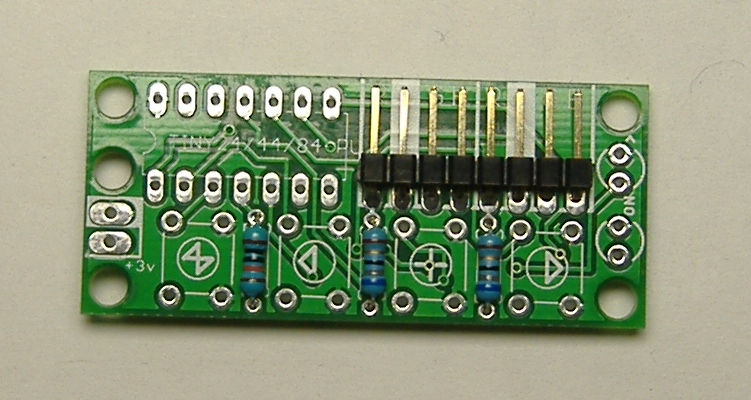
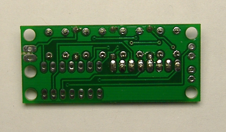
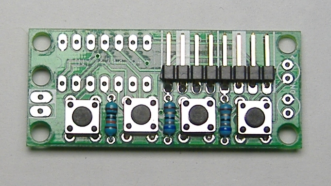
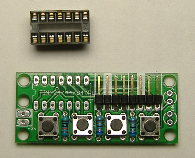
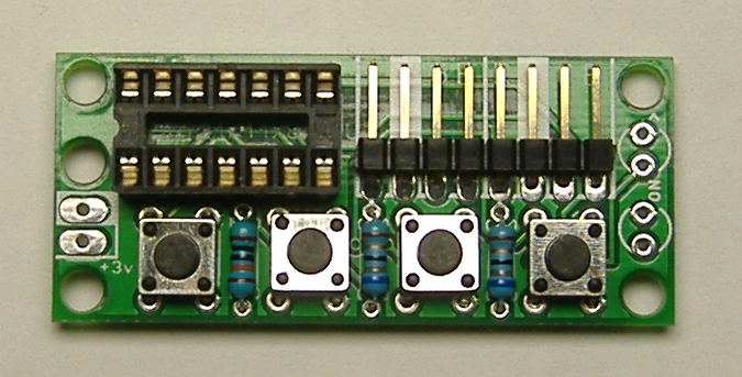
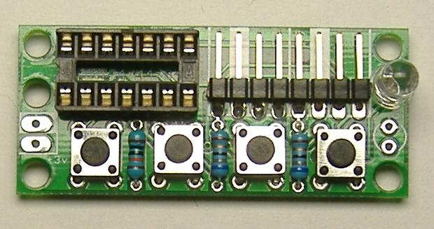
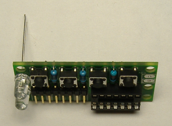
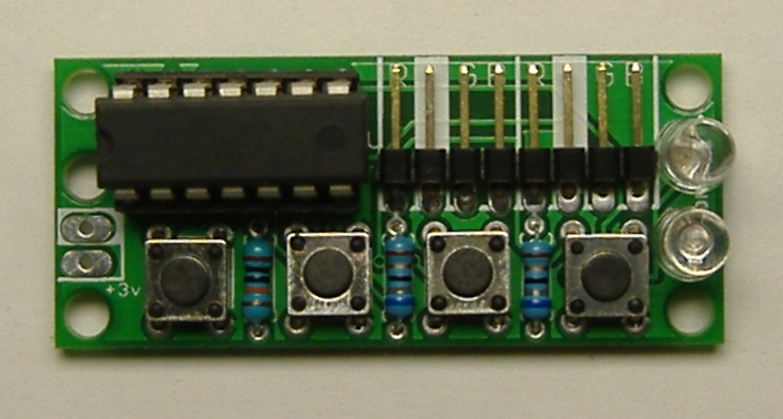
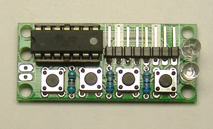
1 Visor controller printed circuit board
1 pre-programmed AtTiny24 microcontroller
1 14 pin DIP chip socket
1 8-pin right angle male header
2 4-pin female jumper cables
2 RGB LEDs
1 Blue LED
1 Ultraviolet LED
2 68 ohm resistors
1 10Kohm resistor
4 tactile switches
1 toggle power switch
1 5" length of 22 gauge wire
Along with your parts bundle, you should have received :
1 pair of welding goggles
2 AAA batteries
You will also need these tools :
A hot glue gun and hot glue sticks
A soldering iron
Solder
Super Glue (optional)
The assembly has been broken down into six stages for your convenience. Follow the instructions in each phase in succession, starting from phase I. Click on the links below to navigate to the instructions for each phase.
Project Stages:
Credits
motivation and logistics
Deren Guler
artwork, visor concept
Austin Redwood
software consulting, laser cutting
Keegan McAllester
kit design and creation
Michael Rule
Original Inspiration
Michael Rule, Matthew Stoffregen, Bard Ermentrout
The assembly has been broken down into six stages for your convenience. Follow the instructions in each phase in succession, starting from phase I. Click on the links below to navigate to the instructions for each phase.
Project Stages:
- The Visor
- Phase I : The Board
- Phase II : The Optics
- Phase III : Holes
- Phase IV : Power
- Phase V : Light
- Phase VI : Finish and Play
- Usage Notes
Credits
Deren Guler
artwork, visor concept
Austin Redwood
software consulting, laser cutting
Keegan McAllester
kit design and creation
Michael Rule