

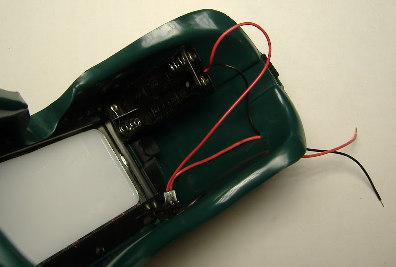
Solder the red (+) wire from the battery pack onto one lead of the power switch, and the red jumper wire onto the other. Insert the power switch into the goggles as shown below.

Next we are going to solder the power wires into the board. Wires that are soldered directly onto the board can break loose. One way to make the connection stronger is to tie the wires to the board before you solder them. We've provided a hole next to the power connection for this purpose. If you find this too challenging, it is not strictly necessary, as there shouldn't be too much strain on the power wires in typical use.

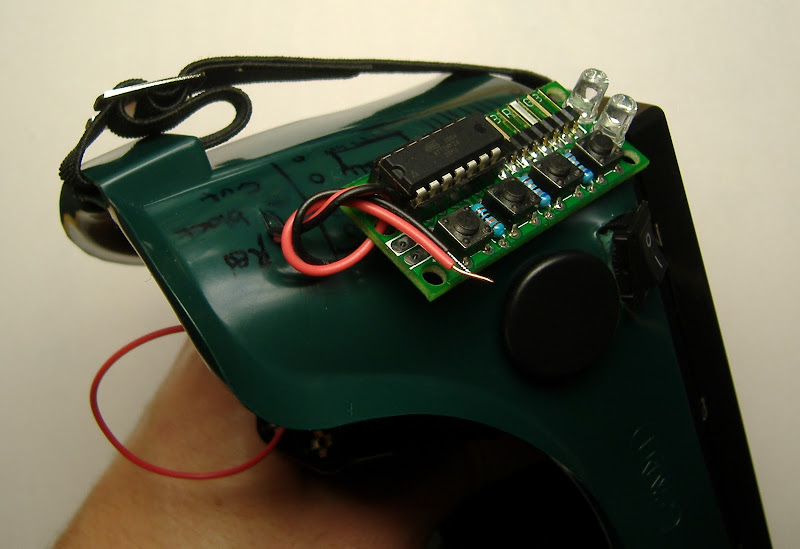

Solder the power cables as shown below, making sure that the red (+) wire goes into the hole labeled "+3v", and the black (-) wire in the other pad with the filled in white marking. Optionally, use the knot trick as shown to reduce strain on this solder connection.


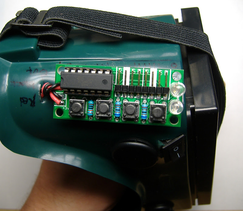
If you have two AAA batteries, you can put them in the battery holder and turn on the power switch to see if the board works. The power-on LED should light up if everything is working correctly. If this does not happen, you will need to troubleshoot the board. Check that the indicator LEDs are inserted in the correct orientation, and that the red (+) wire from the batter is indeed connection to the +3v marked pad on the board. Look for loose or broken solder connections, and make sure the batteries you are using to test are charged.

This completes phase IV.
Project Stages:
- The Visor
- Phase I : The Board
- Phase II : The Optics
- Phase III : Holes
- Phase IV : Power
- Phase V : Light
- Phase VI : Finish and Play
- Usage Notes