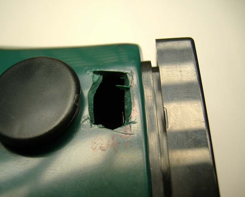
Slide the outer bracket of the goggles, and remove the tinted and clear plastic plates from the welding goggles. Leave the metal bracket.


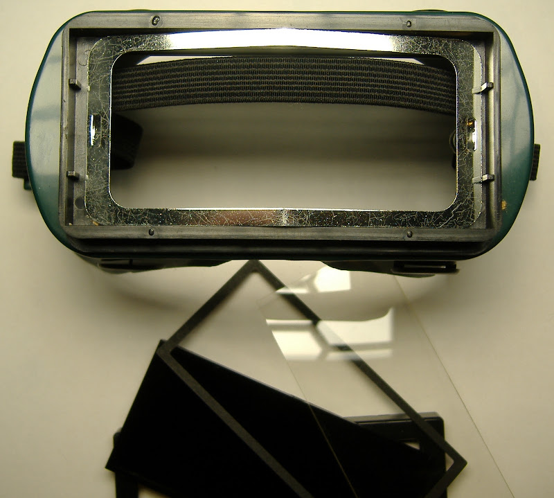
Locate the translucent white plastic pieces that came with your kit. There should be three of them. One has a small notch cut into the side. This notch is for the RGB-LED wires, and this pieces will go on inside later. Another has a picture of some LEDs etched into the surface. This is the inner panel, and you will attach the LEDs to its surface. The third has a decorative pattern etched into its surface. This panel goes on the outside.
(The etching is not shown in these instructions, because the photos were taken before this was added to the design.)
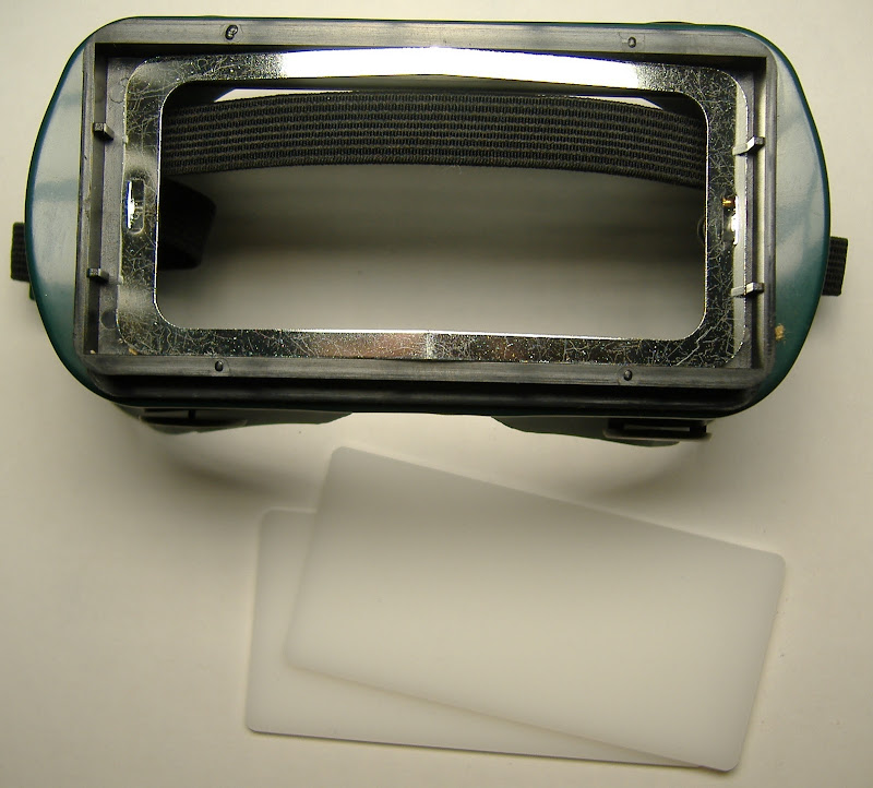
Stack the decorative panel on top of the inner panel, so that the LED markings are on the bottom surface, and the decorative markings are on the top. Place these pieces into the goggles where the tinted plastic used to be, and slide the bracket closed again. You should see a decorative pattern on the front of the goggles, and markings for positioning the LEDs on the inside of the goggles.

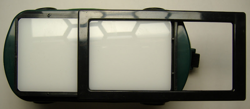
This completes phase II.

Project Stages:
- The Visor
- Phase I : The Board
- Phase II : The Optics
- Phase III : Holes
- Phase IV : Power
- Phase V : Light
- Phase VI : Finish and Play
- Usage Notes